 |
|
 |
The Fundamentals of Orbital Welding
Orbital welding first found use in the 1960's when the aerospace industry recognized the need for a superior joining technique for aircraft hydrolic lines. The solution: a mechanism to rotate a welding arc from a tungsten electrode around a tube-weld joint. Regulating weld current with a control system automated the entire process. The result was a more precise, reliable method than manual welding.
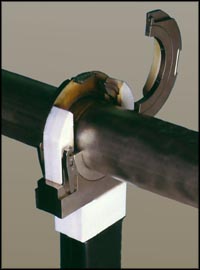 |
| A series of enclosed orbital-weld heads, like the one seen here, join tubing 1/16 to 6 inches in diameter with wall thickness to 0.15 inch. For welding larger-diameter and thicker-wall tube, fabricators opt for open-style weld heads. |
Orbital welding became practical for many industries in the early 1980's with the development of portable combination power supply/control systems that operated from 110-V AC. Modern orbital welding systems offer computer controls that store welding schedules in memory. The skills of a certified welder are thus built into the system, enabling the production of enormous numbers of identical welds and leaving little room for error or defects.
For orbital welding in many precision or high purity applications, the base material, tube diameter(s), weld joint and part fit-up requirements, shielding-gas type and purity, arc length, and tungsten-electrode type, tip geometry, and surface condition may already be written into a specification covering the specific application. In addition, orbital-welding equipment suppliers can offer recommendations on equipment setup and use. For those applications where no specificaton exists, the engineer responsible for welding must create the welding setup and develop the welding procedures.
Orbital welding uses the gas-tungsten-arc-welding (gtaw) process as the source of the electric arc that melts the base material and forms the weld. During gtaw an electric arc forms between a tungsten electrode and the workpiece. To initiate the arc, an RF or high-voltage signal will ionize the shielding gas to generate a path for the weld current. A capacitor dumps current into the arc to reduce arc voltage to a point where the power supply can regulate. The power supply responds to the demand and provides current to maintain the arc.
Sidebar - Industries and Applications for Orbital Welding
Material weldability
In general, the commonly used 300-series stainless steels offer a high degree of weldability using orbital equipment except for Types 303/303SE, which contain additives for ease of machining. The 400-series stainless steels, while generally weldable, may require post-weld heat treatment.
Fabricators should be prepared to adjust the orbital-welding setup to accommodate for potential differences among material heats. The chemical composition of each heat will vary in the concentration of alloying and trace elements, which can affect conductivity and melting characteristics. Minor deviations in elements such as sulfur can affect fluid flow in the weld pool, completely changing the weld profile, while also potentially causing arc wander. When welding on a material from a new heat number, the fabricator should weld a test coupon for the new heat--he may need to make minor changes in amperage to generate the required weld profile.
Weld-joint fitup
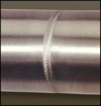 |
| A typical orbital tube weld. Note the overlapping, pulsed-arc finish to the weld surface. |
Fitup is dependent on the weld-specification requirements on tube straightness, weld concavity, reinforcement, and drop through. If no specifications exists, the laws of physics require that the molten material flow and compensate for tube mismatch and any gap in the weld joint.
Differences in tube diameter or out-of-roundness will cause weld-joint mismatch and arc-gap variations from one welding setup to another.
The use of tube and pipe end-prepfacing equipment helps to ensure end squareness and flatness. The i.d. and o.d. should be burr-free with no chamfer.
When two tubes butt together for welding:
- Ensure that no gap exists greater than 5 percent of the wall thickness. While the equipment can handle gaps of 10 percent of wall thickness, or greater in some instances, weld quality and repeatability will suffer.
- Check that the wall thickness and tube alignment varies in the weld zone by no more than plus or minus 5 percent of nominal. Again, the laws of physics will allow welding with mismatch of up to 25 percent of wall thickness, but, again, weld quality and repeatability will suffer.
Avoid alignment mismatch by using engineering stands and clamps to align the two tubes to be welded. This setup also avoids requiring the weld head to force the tubes into alignment.
Shielding-gas basics
Dufing welding, an inert gas directed to the tube o.d. and i.d. prevents the molten material from combining with oxygen in the ambient atmosphere. With sufficient shielding-gas coverage, welds can have zero tint at the weld zone i.d.
Argon is the most commonly used shielding gas, for the o.d. and as the i.d. purge gas. Helium is often used for welding on copper alloys; mixed gases such as 98 Ar-2 H2, 95 Ar-5H2, 90Ar-10 H2, or 75 He-25 Ar find use on heavy wall tube, 0.1 inch and thicker. Using 95 Ar-5 H2 can cause hydrogen embrittlement in welds on carbon steels and some exotic alloys. As a general rule, for simplicity and to minimize shielding-gas costs, use 100 percent argon.
Required gas purity is dictated by the application. For high-purity tasks such as welding of tubing used in semiconductor and pharmaceutical applications, where the concern for micro-contamination is paramount, engineers specify a ultra-high-purity gas or a gas with a local purifier to minimize or eliminate the heat tint. For non critical applications, commercial-grade argon suffices.
Sidebar - Reasons for Using Orbital-Welding Equipment
Tungsten-electrode choice: The right tool for the job
The tungsten electrode, the source of the welding arc, is singularly the most important element of the welding system. While no one would refute the importance of the ignition device on an automobile airbag, the rip cord for a parachute, or quality tires for our automobiles, the importance of the tungsten electrode is often overlooked. Whether in manual or automatic welding, this is one area where metal fabricators can improve the consistency of their welding output with minor effort. By selecting the proper tungsten-electrode type and style, the engineer balances the benefits of a clean arc start and reduced arc wander with good weld penetration and satisfactory electrode life.
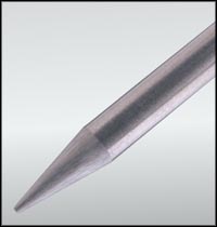 |
| To produce consistent, high-quality welds, the tungsten electrode must be of high-quality material; tip dimensions must be held to close tolerances; and the surface finish--ground or polished--of the electrode must be consistent. |
Electrode Materials: For a long time, tungsten manufacturers have added an oxide to pure tungsten to improve the arc-starting characteristics and the longevity of pure tungsten electrodes. For orbital welding, the most commonly used electrode materials are 2-percent thoriated tungsten and 2-percent ceriated tungsten.
Safety: Many users of the gtaw process do not realize that thorium is a radioactive element—grinding of thoriated-tungsten electrodes generates a radioactive dust. Cerium, as a base material, has lower work function than thorium, thus it offers superior emission characteristics, improving arc-starting ability without the threat of radioactivity.
Electrode Tip Geometry: As more and more companies look for ways to optimize weld quality, process consistency and repeatability become paramount. With the right weld procedure in place, tungsten-electrode shape and quality become two of the next most-important process variables. Fabricators should follow the recommended procedures and electrode specs from their equipment supplier. However, where these specifications do not exist or the engineer would like to adjust the recommended settings to improve and optimize welds, we offer the following guidelines:
- Electrode Taper--This is usually called out in degrees of included angle (usually anywhere between 14 and 60 degrees). Below
is a summary chart that illustrates how taper affects arc shape and performance:
Sharper Electrode Blunter Electrode Last less than blunt Last longer Less penetration Better penetration Wider arc shape Narrower arc shape Handle less Amps Handle more Amps Less arc wande More arc wander More consistent arc Less consistent arc - Electrode Tip Diameter--Grinding an electrode to a point aids arc starting when depositing short-duration welds on small parts.
However, in most cases a flat spot or tip diameter at the end of electrode works best. This reduces erosion at the thin part
of a point and reduces the concern that the tip may fall into the weld. Here's how tip diameter affects welding:
Smaller Tip Larger Tip Easier to start Usually harder to start Less arc wander More arc wander Less electrode life More electrode life Less penetration More penetration
 |
| Electrode taper is usually called out in degrees of included angle, usually anywhere between 14 and 60 degrees. Grinding an electrode to a point aids arc starting when depositing short-duration welds on small parts. However, in most cases a flat spot or tip diameter at the end of electrode works best. |
Tungsten-electrode grinders are now available that provide all of the necessary features for precision grinding at a starting cost of less than $750.00. Pre-ground electrodes are also available so that fabricators can avoid electrode-radioactivity issues and ensure consistent, repeatable electrode material and tip geometry.
Sidebar - Benefits of arc pulsing to orbital welding
The welding procedure
Many welding-equipment suppliers offer a series of pre-engineered weld schedules for a variety of tube diameters, wall thicknesses, and base materials. Welders should always follow these suggested procedures first. However, there will always exist a trade-off in maximum possible weld speed and weld quality and repeatability. Where weld-parameter specifications do not exist or the engineer would like to change those settings, follow these guidelines:
Arc Length Arc-gap setting depends on weld current, arc stability, and tube concentricity or ovality. The welding engineer must keep the electrode at a constant distance from the tube surface with sufficient gap to avoid stubbing out.
As a rule of thumb, set a base arc gap of 0.010 inch and add to this half the tube-wall thickness (or required penetration) expressed in thousandths of an inch. Thus, if the tube wall is 0.030 inch thick, then a good starting arc gap would be 0.010 + 0.015 = .025 inch.
Weld Speed Weld speed depends on flow rate of material to be welded and wall thickness. The objective: to weld as fast as possible while still producing a high-quality weld.
As a starting point, set welding speed at 4 to 10 in./min, running faster on thinner-wall materials and slower on heavy-wall tube.
Welding Current Welding current depends on the base material, wall thickness, weld speed, and shielding gas. The objective: to achieve full penetration defect-free welds.
As a starting point, for welding of stainless steel use 1 A of weld current for every 0.001 inch of wall thickness. Thus, for 0.030-inch-wall tubing, set average weld current to 30 A.
Weld Current Levels Orbital welding typically calls for multiple levels of weld current to compensate for heat buildup in the tube during welding. If the current used to initially penetrate the tubing was held at the same level for the complete weld, penetration would increase as the weld progressed around the tube, resulting in excessive penetration.
Typically, orbital-welding procedures employ a minimum of four levels of weld time, with amperage decreasing from level 1 to level 4.
Arc pulsing minimizes heat input
To pulse the welding arc, the welding power supply rapidly alternates weld current from a high peak current to a low background current. This creates a seam of overlapping welds. This technique reduces overall heat input to the base material and can also allow for increases in travel speed.
During orbital welding, arc pulsing offers another advantage, due to the fact that gravity pulls the weld puddle in different directions as the weld forms around the tube. When pulsing at peak current, the base material melts and flows together. At the lower background current, the puddle can solidify before becoming liquid at the next peak-current pulse. This diminishes the effect of gravity on the molten weld, minimizes weld sagging at the 12 and 6 o'clock positions, and helps prevent the molten weld puddle from running downhill at the 3 and 9 o'clock positions. Thus, arc pulsing becomes more advantageous as wall thickness increases.
Establishing a procedure for pulsed arc welding requires the engineer to set four parameters: peak current, background current, pulse width (duty cycle), and pulse frequency. The ratio of peak current to background current typically varies from 2:1 to 5:1. As a good starting point, try a 3:1 ratio.
Pulse frequency depends on the required weld overlap. As a good starting point, shoot for a 75 percent overlap. On thin-wall tube, set the pulse rate (in pulses per second) equal to the weld-travel speed (in in./min). In other words, if welding progresses at 5 in./min, pulse the weld current at 5 pulses/s.
Pulse width, the portion of the weld cycle where weld current is at peak value, depends on base-material heat sensitivity and available current from the power supply. As material heat sensitivity rises, pulse width must drop. Standard pulse widths range from 20 to 50 percent; as a good starting point, set a pulse width of 35 percent.
|
|
|
About Pro-Fusion
Copyright © 2003-2015 Pro-Fusion by Elderfield & Hall.
10901 McBride Lane
Knoxville TN 37932
Tel: 865.671.7682
Fax: 865.671.7686
email: sales@pro-fusiononline.com
Privacy Policy, Shipping, Terms & Conditions