 |
|
 |
Fundamentals of Orbital Tube Welding
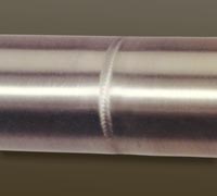 |
| A typical orbital tube weld. Note the pulsed arc finish on the weld surface. |
Understanding the basic principles behind orbital tube welding may help you arrive more rapidly at the optimum weld procedure for your specific application.
Orbital welding was first used in the 1960's when the aerospace industry recognized the need for a superior joining technique for aerospace hydraulic lines. A mechanism was developed in which the arc from a tungsten electrode was rotated around the tubing weld joint. The arc welding current was regulated with a control system thus automating the entire process. The result was a more precision and reliable method than the manual welding method it replaced.
Orbital welding became practical for many industries in the early 1980's when combination power supply/control systems were developed that operated from 110 VAC and were physically small enough to be carried from place to place on a construction site for multiple in-place welds. Modern day orbital welding systems offer computer control where welding parameters for a variety of applications can be stored in memory and called up when needed for a specific application. The skills of a certified welder are thus built into the welding system, producing enormous numbers of identical welds and leaving significantly less room for error or defects.
 |
| Standard enclosed orbital weld heads are practical in welding tube sizes from 1/16 inch (1.6mm) to 6 inches (152mm) with wall thickness' of up to .154 inches (3.9mm) Larger diameters and wall thickness' can be accommodated with open style weld head. |
Orbital Welding Equipment
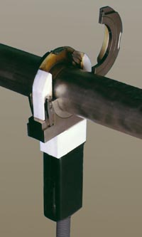
In the orbital welding process, tubes/pipes are clamped in place and an orbital weldhead rotates an electrode and electric arc around the weld joint to make the required weld. An orbital welding system consists of a power supply and an orbital weldhead.
Power Supply: The power supply/control system supplies and controls the welding parameters according to the specific weld program created or recalled from memory. The power supply provides the control parameters, the arc welding current, the power to drive the motor in the weld head and switches the shield gas(es) on/off as necessary.
Weld Head: Orbital weld heads are normally of the enclosed type and provide an inert atmosphere chamber that surrounds the weld joint. Standard enclosed orbital weld heads are practical in welding tube sizes from 1/16 inch (1.6mm) to 6 inches (152mm) with wall thickness' of up to .154 inches (3.9mm) Larger diameters and wall thickness' can be accommodated with open style weld heads.
Reasons for Using Orbital Welding Equipment
There are many reasons for using orbital welding equipment. The ability to make high quality, consistent welds repeatedly at a speed close to the maximum weld speed offer many benefits to the user:
- Productivity. An orbital welding system will drastically outperform manual welders, many times paying for the cost of the orbital equipment in a single job.
- Quality. The quality of a weld created by an orbital welding system with the correct weld program will be superior to that of manual welding. In applications such as semiconductor or pharmaceutical tube welding, orbital welding is the only means to reach the weld quality requirements.
- Consistency. Once a weld program has been established an orbital welding system can repeatedly perform the same weld hundreds of times, eliminating the normal variability, inconsistencies, errors and defects of manual welding.
- Skill level. Certified welders are increasingly hard to find. With orbital welding equipment you don't need a certified welding operator. All it takes is a skilled mechanic with some weld training.
- Orbital welding may be used in applications where a tube or pipe to be welded cannot be rotated or where rotation of the part is not practical.
- Orbital welding may be used in applications where access space restrictions limit the physical size of the welding device. Weld heads may be used in rows of boiler tubing where it would be difficult for a manual welder to use a welding torch or view the weld joint.
- Many other reasons exist for the use of orbital equipment over manual welding. Examples are applications where inspection of the internal weld is not practical for each weld created. By making a sample weld coupon that passes certification, the logic holds that if the sample weld is acceptable, that successive welds created by an automatic machine with the same input parameters should also be sound.
Industries and Applications for Orbital Welding
Aerospace: As noted earlier, the aerospace industry was the first industry to recognize the requirement for orbital welding. The high pressure systems of a single plane can have over 1,500 welded joints, all automatically created with orbital equipment.
Boiler Tube: Boiler tube installation and repairs offer a perfect application for orbital welding. Compact orbital weld heads can be clamped in place between rows of heat exchanger tubing where a manual welder would experience severe difficulty making repeatable welds.
Food, Dairy and Beverage Industries: The food, dairy and beverage industries require consistent full penetration welds on all weld joints. Most of these tubing/piping systems have schedules for cleaning and sterilization in place. For maximum piping system efficiency the tubing must be as smooth as possible. Any pit, crevice, crack or incomplete weld joint can form a place for the fluid inside the tubing to be trapped and form a bacteria harbor.
Nuclear Piping: The nuclear industry with its severe operating environment and associated specifications for high quality welds has long been an advocate of orbital welding.
Offshore Applications: Sub-sea hydraulic lines use materials whose properties can be altered during the thermal changes that are normal with a weld cycle. Hydraulic joints welded with orbital equipment offer superior corrosion resistance and mechanical properties.
Pharmaceutical Industry: Pharmaceutical process lines and piping systems deliver high quality water to their processes. This requires high quality welds to ensure a source of water from the tubes that is uncontaminated by bacteria, rust or other contaminant. Orbital welding ensures full penetration welds with no overheating occurring that could undermine the corrosion resistance of the final weld zone.
Semiconductor Industry: The semiconductor industry requires piping systems with extremely smooth internal surface finish in order to prevent contaminant buildup on the tubing walls or weld joints. Once large enough, a build up of particulate, moisture or contaminant could release and ruin the batch process.
Tube/Pipe Fittings, Valves and Regulators: Hydraulic lines, and liquid and gas delivery systems all require tubing with connector fittings. Orbital systems provide a means to ensure high productivity of welding and improved weld quality. Sometimes the tubing may be welded in place to a valve or regulator body. Here the orbital weldhead provides the ability to produce high quality welds in applications with restricted access to the weld joint.
General Guidelines for Orbital Tube Welding
For orbital welding in many precision or high purity applications, the base material to be welded, the tube diameter(s), weld joint and part fit-up requirements, shield gas type and purity, arc length, and tungsten electrode material, tip geometry and surface condition may already be written into a specification covering the specific application.
Each orbital welding equipment supplier differs slightly in recommended welding practices and procedures. Where possible, follow the recommendations of your orbital equipment supplier for equipment set-up and use, especially in areas that pertain to warranty issues.
This section is intended as a guideline for those applications where no specification exists and the engineer responsible for the welding must create the welding set-up, and derive the welding parameters in order to arrive at the optimum welding solution.
Welding Basics and Set-Up
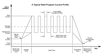 |
| This weld profile shows a single level of weld time. Orbital welding normally uses a minimum of 4 levels of weld time with each level decreasing in weld amperage as the tube heats up during the welding process. |
The Physics of the GTAW Process
The orbital welding process uses the Gas Tungsten Arc Welding process (GTAW) as the source of the electric arc that melts the base material and forms the weld. In the GTAW process (also referred to as the Tungsten Inert Gas process - TIG) an electric arc is established between a Tungsten electrode and the part to be welded. To start the arc, an RF or high voltage signal (usually 3.5 to 7 KV) is used to break down (ionize) the insulating properties of the shield gas and make it electrically conductive in order to pass through a tiny amount of current. A capacitor dumps current into this electrical path, which reduces the arc voltage to a level where the power supply can then supply current for the arc. The power supply responds to the demand and provides weld current to keep the arc established. The metal to be welded is melted by the intense heat of the arc and fuses together.
Material Weldability
The material selected varies according to the application and environment the tubing must survive. The mechanical, thermal, stability, and corrosion resistance requirements of the application will dictate the material chosen. For complex applications a significant amount of testing will be necessary to ensure the long term suitability of the chosen material from a functionality and cost viewpoint.
In general, the most commonly used 300 series stainless steels have a high degree of weldability with the exception of 303/303SE which contain additives for ease of machining. 400 series stainless steels are often weldable but may require post weld heat treatment.
Accommodation must be made for the potential differences of different material heats. The chemical composition of each heat batch number will have minor differences in the concentration of alloying and trace elements. These trace elements can vary the conductivity and melting characteristics slightly for each heat. When a change in heat number is made a test coupon should be made for the new heat. Minor changes in amperage may be required to return the weld to its original profile.
It is important that certain elements of the material be held to close tolerances. Minor deviations in elements such as sulfur can vary the fluid flow in the weld pool thus completely changing the weld profile and also causing arc wander.
 |
|
| Low Sulfur Content (less than .01% - 100 PPM) Surface tension temperature coefficient negative |
Normal Sulfur Content (greater than .01% - 100 PPM) Surface tension temperature coefficient positive |
| Minor changes in sulfur content can change weld pool flow characteristics with a dramatic effect on penetration (the Maragoni effect) | |
Weld Joint Fit-Up
Weld joint fit-up is dependent on the weld specification requirements on tube straightness, weld concavity, reinforcement and drop through. If no specification exists the laws of physics will require that the molten material flow and compensate for tube mismatch and any gap in the weld joint.
Tubing is produced according to tolerances that are rigid or loose according to the application for which the tube was purchased. It is important that the wall thickness is repeatable at the weld joint from part to part. Differences in tube diameter or out-of-roundness will cause weld joint mismatch and arc gap variations from one welding set up to another.
Tube and pipe end prep facing equipment is recommended in order to help ensure end squareness and end flatness. Both the ID and OD should be burr free with no chamfer.
When two tubes are butted together for welding, two of the main considerations are mismatch and gaps. In general, the following rules apply:
- Any gap should be less than 5% of the wall thickness. It is possible to weld with gaps of up to 10% (or greater) of wall thickness, but the resultant quality of weld will suffer greatly and repeatability will also become a significant challenge.
- Wall thickness variations at the weld zone should be +/- 5% of nominal wall thickness. Again, the laws of physics will allow welding with mismatch of up to 25% of wall thickness if this is the only challenge but again, the resultant quality of weld will suffer greatly and repeatability will also become a significant issue.
- Alignment mismatch (high-low) should be avoided by using engineering stands and clamps to align the two tubes to be welded. This system also removes the mechanical requirement of aligning the tubes from the orbital weldhead.
Shield Gas(es)
An inert gas is required on the tube OD and ID during welding to prevent the molten material from combining with the oxygen in the ambient atmosphere. The objective of the welder should be to create a weld which has zero tint at the weld zone ID.
Argon is the most commonly used shield gas (for the OD of the tube)and the purge gas (for the ID of the tube). Helium is often used for welding on copper material. Mixed gases such as 98% Argon/2% Hydrogen, 95% Argon/5% Hydrogen, 90% Argon/10% Hydrogen or 75% Helium/25% Argon my be used when the wall thickness to be welded is heavy (.1" or above). Using mixtures of 95% Argon/5% Hydrogen is incompatible with carbon steels and some exotic alloys, often causing hydrogen embrittlement in the resultant weld. As a general rule, for simplicity and reduction of shield gas cost, use 100% argon gas.
Gas purity is dictated by the application. For high purity situations where the concern for micro-contamination is paramount, such as semiconductor and pharmaceutical applications, the shield and purge gases must minimize the heat tint that could otherwise be undesirable. In these applications, ultra high purity gas or gas with a local purifier are employed. For non-critical applications, commercial grade argon gas may be used.
Tungsten Electrode
The tungsten welding electrode, the source of the welding arc, is one of the most important elements of the welding system that is most commonly ignored by welding systems users. While no one would refute the importance of the ignition device on an automobile airbag, the rip cord for a parachute, or quality tires for automobiles, the importance of tungsten electrode for quality welding is often overlooked. Users continue to manually grind and wonder why they produce inconsistent results. Whether in manual or automatic welding, this is the area where manufacturing organizations can improve the consistency of their welding output with minor effort.
The objective for the choice of tungsten parameters is to balance the benefits of a clean arc start and reduced arc wander with good weld penetration and a satisfactory electrode life.
Electrode Materials: For quite some time, tungsten manufacturers have added an oxide to pure tungsten to improve the arc starting characteristics and the longevity of pure tungsten electrodes. In the orbital welding industry, the most commonly used electrode materials are 2% thoriated tungsten and 2% ceriated tungsten.
Safety: The safety issues of tungsten electrode material are now being looked at more closely. Many users of the Tig welding process do not realize that the welding electrode they use contains Thorium, a radioactive element added to the tungsten. While the radioactivity is of a low level, it brings an issue of danger especially with the radioactive dust generated when grinding the electrodes to a point for welding.
Alternative, non-radioactive tungsten materials are now available, such as 2% ceriated electrodes, which often offer superior arc welding. While these materials are commercially available they have been largely ignored until recently.
Recommended Electrode Materials: Cerium, as a base material, has a lower work function than thorium, thus it offers superior emission characteristics. Thus, not only do ceriated electrodes offer an advance in electrode safety, they also improve the arc starting ability of the orbital equipment. However, as mentioned earlier, it is always best to follow the advice of your orbital equipment manufacturer. 2% ceriated and 2% thoriated electrodes are the most commonly recommended materials for orbital welding equipment.
Electrode Tip Geometry: Given the ever increasing weld quality requirements of the final weld, more and more companies are looking for ways to ensure that their weld quality is up to par. Consistency and repeatability are key to welding applications. The shape and quality of the tungsten electrode tip is finally being recognized as a vital process variable. Once a weld procedure has been established, it is important that consistent electrode material, tip geometry and surface condition be used.
Welding Basics and Set-Up
 |
To produce high consistent welds the Tungsten
electrode must provide the following:
|
Welders should follow an equipment supplier's suggested procedures and dimensions first, because they have usually performed a significant amount of qualifying and troubleshooting work to optimize electrode preparation for their equipment. However, where these specifications do not exist or the welder or engineer would like to change those settings to possibly improve and optimize their welding, the following guidelines apply:
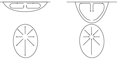
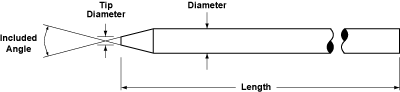
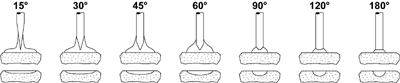
- Electrode Taper - This is usually called out in degrees of included angle (usually anywhere between 14° and 60°). Below is a summary chart that illustrates how different tapers offer different arc shapes and features:
- Electrode Tip Diameter - Grinding an electrode to a point is sometimes desirable for certain applications, especially where arc starting is difficult or short duration welds on small parts are performed. However in most cases it is best for a welder to leave a flat spot or tip diameter at the end of electrode. This reduces erosion at the thin part of a point and reduces the concern that the tip may fall into the weld. Larger and smaller tip diameters offer the following trade-offs:
| Sharper Electrodes | Blunter Electrodes |
| Easy arc starting | Usually harder to start the arc |
| Handle less amperage | Handle more amperage |
| Wider arc shape | Narrower arc shape |
| Good arc stability | Potential for more arc wander |
| Less weld penetration | Better weld penetration |
| Shorter electrode life | Longer electrode life |
In addition, to demonstrate graphically how the taper selection will effect the size of the weld bead and the amount of penetration, below is a drawing that shows typical representations of the arc shape and resultant weld profile for different tapers.
| Smaller Tip | Larger Tip |
| Easier arc starting | Usually harder to start the arc |
| Potential for more arc wander | Good arc stability |
| Less weld penetration | More weld penetration |
| Shorter electrode life | More electrode life |
Tungsten Electrode Grinders and Pre-Ground Electrodes: Using electrodes pre-ground to requirements or a dedicated commercial electrode grinder to provide electrode tip quality and consistency offers the following benefits to the user in their welding process:
- Improved arc starting, increased arc stability and more consistent weld penetration.
- Longer electrode life before electrode wear or contamination.
- Reduction of tungsten shedding. This minimizes the possibility of Tungsten inclusions in the weld.
- A dedicated electrode grinder helps ensure that the welding electrodes will not become contaminated by residue or material left on a standard shop grinder wheel.
- Tungsten electrode grinding equipment requires less skill to ensure that the tungsten electrode is ground correctly and with more consistency.
 |
| Using pre-ground electrodes ensures that the electrode material quality, tip geometry and ground electrode surface input to the welding process is constant |
Pre-Ground Electrodes: Rather than risk electrode radioactivity issues and also constantly endure the variability of each operator grinding the electrodes with a slightly different touch, many manufacturing organizations have chosen to purchase electrodes pre-ground. In addition, since a small difference in the dimensions of an orbital electrode can produce a big difference in the weld results, pre-ground electrodes are the preferred electrode choice to maintain the consistency of your welding. This low cost option ensures that the electrode material quality, tip geometry and ground electrode surface input to the welding process is constant. Consult electrode charts or a pre-ground electrode supplier to obtain the electrode diameter and tip geometry that is most suitable for your welding application.
Welding Parameter Development
Many welding equipment suppliers offer a series of pre-calculated weld programs for a variety of tube diameters, wall thicknesses and materials. Welders should always follow an equipment supplier's suggested procedures first, because they have usually performed a significant amount of qualifying and troubleshooting work to optimize electrode preparation for their equipment.
However, it is impossible for the equipment suppliers to have welding procedures for every welding application and there will always exist a trade off in maximum weld speed possible versus weld quality and repeatability. Where weld parameter specifications do not exist or the welder or engineer would like to change those settings to possibly improve or optimize their welding, the guidelines noted below give information on how to modify the welding parameters for a desired result.
Note: The "rules of thumb" noted below are general guidelines only and will not apply to every welding application and mix of parameters chosen. Although the welding parameters are often chosen and changed according to the specific needs of the application, there are some industry standards that have been developed as starting points. Experimentation and experience will determine the final weld parameters.
Arc Length
The arc gap setting is dependent on weld current, arc stability and tube concentricity/ovality. The objective of the welding engineer is to keep the electrode at a constant distance from the tube surface with sufficient gap to avoid stubbing out.
As a "rule of thumb" use a base arc gap of 0.010" and add to this half the penetration required (usually the tube wall thickness) expressed in thousandths of an inch. Thus if the tube wall is .030" then a good starting arc gap would be 0.010" + 0.015" = .025". For a wall thickness/penetration requirement of .154" the arc gap would be 0.010" + .070" = 0.080"
Weld Speed
The weld speed is dependent on flow rate of material to be welded, and wall thickness. The objective is to weld as fast as possible while still yielding a quality output.
As a starting point the tungsten surface speed should be 4 - 10 inches per minute with the faster welding speeds used for thinner wall materials and the slower welding speeds used for heavy wall thickness. As a good starting point, use 5 inches per minute.
Welding Current
The welding current is dependent on the material to be welded, wall thickness, weld speed, and the shield gas chosen. The objective is to achieve full penetration, defect free welds.
As a starting point use 1 average current per 0.001" wall thickness if the material is stainless steel. Thus for a 0.030" wall tubing the average weld current will be 30 amps in the first level.
Weld Current Levels
Orbital welding normally uses multiple levels of weld current to compensate for heat building up in the tube during the welding process. If the weld current used to initially penetrate the tubing was held at the same level for the complete weld, the weld penetration would increase as the weld progressed around the tube, producing too much penetration.
Normally orbital welding uses a minimum of 4 levels of weld time with each level decreasing in weld amperage
Starting parameters: Set weld level 4 to be at 80% of weld level 1 amperages. Set weld level 2 and weld level 3 to gradually decrease the current from level 1 to level 4.
Arc Pulsing
Arc pulsing involves using the welding power supply to rapidly alternate the weld current from a high (peak current) to a low (background current) value. This creates a seam of overlapping spot welds. This technique reduces the overall heat input to the base material and can also allow for increases in weld speed. This welding technique brings many benefits to the welding procedure, often improving weld quality and repeatability. In some cases materials and weld joints with poor fit-up that are difficult to successfully weld with a non-pulsed arc can easily be welded with a pulsed arc technique. The result is improved weld quality and increased output.
In orbital welding, arc pulsing also offers another advantage due to the fact that the gravity pulls the weld puddle in different directions as the weld is created around the tube. When pulsing at peak current the base material(s) melt and flow together, at the lower background current the puddle can solidify before becoming liquid at the next peak current pulse. This diminishes the effect of gravity on the molten weld, minimizes the weld sagging at the 12 and 6 o clock positions, and reduces the molten weld puddle running/slumping downhill at the 3 and 9 o'clock positions and effectively alters the electrode to weld puddle distance. The arc pulsing technique thus becomes more advantageous as the wall thickness increases resulting in a larger weld puddle.
Arc Pulsing Parameters: Arc pulsing involves four welding parameters: peak current, background current, pulse width (duty cycle), and pulse frequency. Here again, opinions vary from one welding organization to another and indeed from welder to welder. Many welders arrive at the same welding result having somewhat different welding parameters.
It is important to understand how to choose convenient weld development starting parameters and the effect on the weld by changing each parameter.
The primary objective is to use the benefits of weld pulsation to improve weld quality and output.
Peak/Background Current Ratios: The peak to background current ratios basically provide a means for the welding current to pulse from one level to another. Industry usage generally varies from 2:1 ratios to 5:1 ratios. A good starting point is to use 3:1 ratios, make the required weld and test other parameters to see if any benefit can be gained.
Pulse Frequency: The pulse frequency is dependent on spot overlap required. Good starting parameters are to attempt for a 75% spot overlap. Pulse rate for thin wall tube is often equal to the weld speed in ipm (5 ipm = 5 pps)
Pulse Width: The pulse width (the percentage of time spent on the peak current) is dependent on heat sensitivity of material and available current from power supply. Higher heat sensitivity requires lower pulse width % on peak current. Standard pulse widths are often 20% to 50%. A good starting parameters would be to set a pulse width of 35%.
Free arc pulsation software is available from the internet that pre-calculates a variety of arc pulsation parameters for any given amperage of an application. In this fashion, welders can arrive at an acceptable weld program and quickly obtain a variety of alternative arc pulsation options to examine without requiring lengthy calculations or tedious empirical "try it and see" test welding.
Conclusion
One of the best methods for a company to assume a superior position in the marketplace is to develop a competitive advantage by optimizing the welding process in manufacturing. This will improve weld quality, increase weld speed, and reduce scrap and rework costs. From this, a company can realize lower costs per unit of product, quicker delivery of product, and less defects in workmanship. All of this can be accomplished through the use of orbital welding systems using the consistency and repeatability of fine-tuned weld programs, control of input material and shield gas quality, and properly prepared pre-ground electrodes.
Pro-Fusion Technologies provides pre-ground tungsten electrodes for orbital and tube mill applications. The company offers free access to a welding web site with over 75% of the site dedicated to offering information on welding processes and even allows the user to input data on what they are welding and receive welding parameters. The site also gives information on various welding applications with recommendations on the best techniques to use and handbooks for troubleshooting welding systems. The web site may be accessed at www.Pro-fusionOnline.com
For free sample Tungsten electrodes, or more information on any of the above contact Pro-Fusion, 1090 Lawrence Drive #104, Newbury Park, CA 91320 U.S.A. Tel (805) 376-8021 Fax (805) 376-0619 Email: Sales@Pro-FusionOnline.com
Welding Parameter Development Example
For 1" Tube/.030" Tube Wall Thickness:
- Arc Length/Gap = .010" + (0.5 x penetration required)
Starting Parameters: .010" + (0.5 x .030") = .025"
- Weld Speed = 5 ipm surface speed
RPM = ipm/(3.1415 x dia.)
Starting Parameters: 5/(3.1415 x 1") = 1.59 RPM
- Welding Current Levels
Level 1 = 1 amp per .001" of wall thickness for level 1 current
Level 4 = 80% of Level 1 current
Levels 2 and 3 gradually decrease the current from Level 1 to Level 4
Starting Parameters:
Level 1 Peak Current = .030" wall thickness = 30 amps
Level 4 Peak Current = 30 amps x 80% = 24 amps
Level 2 Peak Current = 28 amps
Level 3 Peak Current = 26 amps
Background Current will be 1/3rd of peak current. Pulse width/duty cycle is 35%
- Tungsten Electrode Diameter & Tip Geometry - Use your equipment manufacturer's specifications or consult your pre-ground electrode supplier
The above data gives starting parameters. On completion of the first test weld, the parameters will be modified to obtain the final result desired.
We can provide free samples of various tungsten materials, electrode tip geometries, and surface finishes for you to test. Call or e-mail to review your specific application and to obtain the most suitable samples for your needs.
About Pro-Fusion
Copyright © 2003-2015 Pro-Fusion by Elderfield & Hall.
10901 McBride Lane
Knoxville TN 37932
Tel: 865.671.7682
Fax: 865.671.7686
email: sales@pro-fusiononline.com